Introduction
Geometric Dimensioning and Tolerancing (GD&T) is a powerful tool for conveying design intent and ensuring precision in manufacturing. However, incorrect usage of GD&T symbols and improper interpretation of feature control frames can lead to significant errors. In this blog, we will explore some of the most common mistakes made in GD&T and provide practical tips to avoid them.
Mistake 1: Misinterpreting Datum Features
A common error in GD&T is incorrectly identifying or using datum features. Datums serve as the reference points for measurements, and selecting the wrong datum can lead to dimensional inaccuracies and assembly problems. How to Avoid: Ensure that datum features are clearly marked and accurately represent the most functional parts of the component. Conduct a thorough analysis to determine which surfaces will serve as the most stable and repeatable references.
Mistake 2: Over-Tolerancing
Overly tight tolerances can increase production costs and reduce manufacturability without significantly improving part quality. Applying unnecessary geometric tolerances often results in higher machining costs and inspection difficulties. How to Avoid: Apply tolerances only where they are functionally necessary. Use basic dimensions for less critical features to minimize production challenges.
Mistake 3: Confusing Symbols and Annotationsolerancing
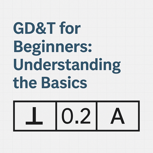
GD&T involves a wide range of symbols, and using the wrong one can convey incorrect information to manufacturers and inspectors. For example, mixing up flatness and parallelism can result in significant measurement errors. How to Avoid: Familiarize yourself with the key GD&T symbols and their meanings. Practice interpreting drawings and using symbol charts as references when designing.
Mistake 4: Ignoring Material Condition Modifiers
Material condition modifiers, like Maximum Material Condition (MMC) and Least Material Condition (LMC), play an important role in tolerancing. Ignoring these can lead to flawed designs and improper part fits. How to Avoid: Always consider the function of the part when applying material condition modifiers. Use MMC and LMC where appropriate to allow for maximum manufacturing flexibility.
Mistake 5: Inconsistent Use of Feature Control Frames
Inconsistency between feature control frames and actual part geometry is a frequent issue. If the feature control frame does not match the intended function, it can cause confusion during inspection. How to Avoid: Double-check that the feature control frames are consistent with the part design and intended functional requirements. Involve both designers and quality control engineers in the drawing review process.
Conclusion
Avoiding these common GD&T mistakes requires a solid understanding of both the theoretical and practical aspects of the system. Regular training and practice can help engineers and technicians interpret and apply GD&T correctly, ultimately leading to improved precision, efficiency, and product quality.